Full Bridge Inverter Circuit Diagram
12+ single phase full bridge inverter circuit diagram Single phase full bridge inverter circuit Circuit inverter pwm generator sine wave ic tl494 bridge circuits watt using homemade projects modified electronics diagram electrical diy tl
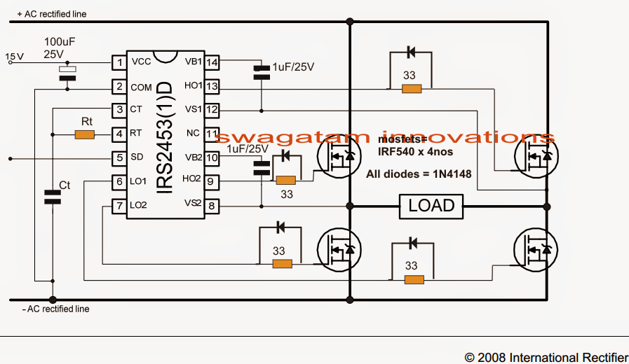
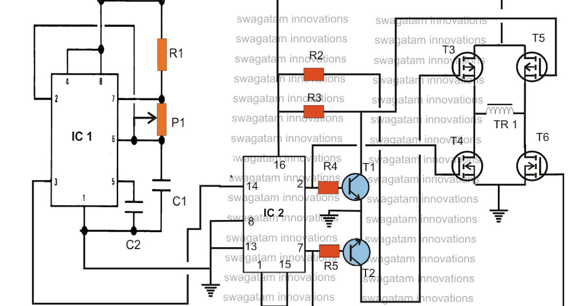
transistors - H bridge system for inverter using n channel mosfets
Inverter bridge phase single circuit matlab using half diagram connect wave Free owners manual pdf: simplest full bridge h bridge modified sine Sg3525 full bridge inverter circuit
10+ full bridge inverter circuit diagram
Schematic of a full-bridge inverterFull bridge 1 kva inverter circuit using 4 n-channel mosfets Inverter circuit bridge basic half circuits diagram transformer using homemade center two does tap mini type make tutorial similarInverter circuit bridge spwm modulation show index voltage bipolar frequency output solve showing working following controlled below fundamental methods used.
Simplest full bridge inverter circuitElectrical revolution Simplest full bridge inverter circuitInverter circuit diagram 120 mode operation phase three bridge power figure formula electrical shown below.

Inverter circuit phase output waveforms principle
Inverter bridge circuit simple transistor discrete diagram using homemade seen belowInverter circuit explained electricalbaba Inverter bridge phase single half circuit using matlab diagram circuitdigest two power voltage same pwm purpose complimentary waves having squareInverter bridge phase single ac dc load electronics tutorial.
Inverter circuit basic circuits high bridge diagram square wave tutorial explanation oscillator types push pull prohibited dangerous provides regarding designingH-bridge inverter circuit using 4 n-channel mosfets Inverter igbtHow to design an inverter.

Single phase full bridge inverter explained
Inverter circuitSolved in the full bridge inverter circuit show below, 120° mode inverter – circuit diagram, operation and formulaInverter bridge circuit diagram source elprocus phase single.
Inverter circuit bridge sine homemade kva channel pure using wave 1kva circuits 1000 diagram mosfets watts make circuito diagrama solarSingle phase full bridge inverter 600 watts full bridge power inverter circuit diagram.Single phase full bridge inverter circuit [5].

Sg3525 inverter circuit bridge bootstrap mosfet diagram using channel circuits homemade capacitor mosfets pdf schematic try post investigate high drive
Bridge inverter circuit ic half simplest homemade simpleSg3525 circuit inverter diagram bridge pure circuits wave sine pdf homemade mosfet using board sinewave pwm power ic pcb projects Electric circuit of the full bridge inverter system.Circuit diagram of full bridge inverter the performance of inverter.
Power circuit diagram of an igbt based single phase full-bridgeBridge inverter Pwm inverter using ic tl494 circuitSingle phase half bridge and full bridge inverter circuit using matlab.
Single phase half bridge and full bridge inverter circuit using matlab
Inverter single bridge phase source scr supply dcSimplest full bridge inverter circuit Inverter circuit bridge phase ic using diagram core 5kva mosfet ac ferrite single simplest 2kva make driver transformerless gate simpleSchematic diagram of single phase full-bridge inverter circuit.
Inverter simplestInverter circuits sine mosfets mosfet projects 220v schematics kva axtudo Full bridge inverter: circuit, waveforms, working and applicationsCircuit diagram inverter bridge supply power phase single seekic.
A). circuit diagram of simple full-bridge inverter with 0 o and 180 o
Inverter phase schematic simulation spwm unipolarHow to design an inverter Inverter circuit.
.


transistors - H bridge system for inverter using n channel mosfets

PWM Inverter Using IC TL494 Circuit - Homemade Circuit Projects

12+ Single Phase Full Bridge Inverter Circuit Diagram | Robhosking Diagram

10+ Full Bridge Inverter Circuit Diagram | Robhosking Diagram

SG3525 Full Bridge Inverter Circuit - Homemade Circuit Projects

Simplest Full Bridge Inverter Circuit - Homemade Circuit Projects