Full Wave Rectifier Circuit Diagram
Rectifier study Full_wave_rectifier Rectifier wave circuit working diagram types theory
Dictionary of Electronic and Engineering Terms, Full-Wave Rectifier circuit
Wave rectifier diode voltage waveform circuit tutorial circuits Full wave bridge rectifier circuit [multisim simulation] Full wave rectifier circuit working and theory
Wave rectifier circuit diagram seekic signal ic rectification
Rectifier principleWhat is half wave and full wave rectifier? Rectifier wave circuit theory capacitor load working rl calculate diagram bridge half output schematic dc typesRectifier circuit diagram.
Rectifier circuit diagramFull wave rectifier – circuit diagram and working principle » electroduino Rectifier wave working center tap circuit diagram advantages disadvantagesFull wave rectifier : circuit diagram, types, working & its applications.

Rectifier waveform input
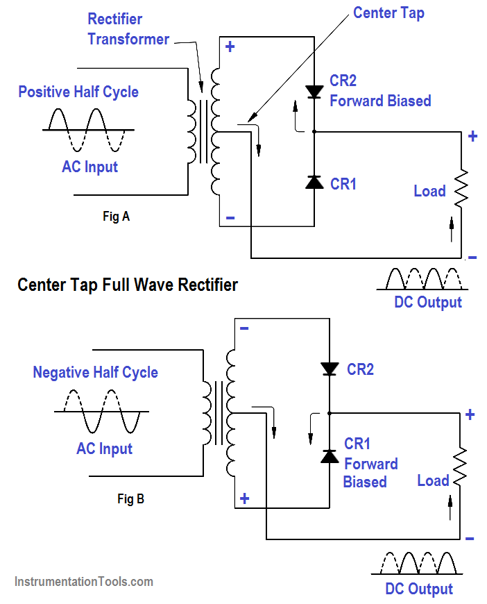
Full wave rectifier circuit diagram (center tapped & bridge rectifier)Rectifier wave Half wave & full wave rectifier: working principle, circuit diagramRectifier transformer waveform tapped etechnog.
Precision full wave rectifier circuit diagramFull wave bridge rectifier circuit diagram Schematic structure of the full-wave rectifier under study.What is full wave rectifier ?.

Rectifier waveform tapped dc load voltage capacitor
Precision rectifier circuit using opamp working and applicationsRectifier wave circuit tap center half Rectifier wave circuit filter without diagram bridge capacitor diodes tapped center type circuits below board four electronic using circuitdigest addedRectifier precision circuit opamp tutorial electronics.
Full-wave rectifierExplain briefly, with the help of circuit diagram, the working of a Rectifier bridge wave circuit diagram regulator icFull-wave rectifier circuit.

Rectifier wave diagram circuit explain briefly draw input output working its help waveforms class diode kb table cycle
Rectifier circuit wave diode terms diagram dictionary electronic engineeringPrecision rectifier circuit using opamp working and applications Rectifier wave precision circuit diagram circuitsstream sourcedDictionary of electronic and engineering terms, full-wave rectifier circuit.
Rectifier opamp diodeRectifier circuit: half wave and full wave rectifier working principle Build a full wave rectifier circuit diagramSingle phase half wave rectifier- circuit diagram,theory & applications.

Rectifier diode voltage rectification diodes operation supply zener regulator detector
Full wave rectifier tutorial and circuitsRectifier wave bridge circuit multisim diagram simulation diodes .
.


What is Half Wave and Full Wave Rectifier? - Operation & Circuit

Explain briefly, with the help of circuit diagram, the working of a

Full Wave Rectifier : Circuit Diagram, Types, Working & Its Applications
Full-Wave Rectifier Circuit - Inst Tools

Schematic structure of the full-wave rectifier under study. | Download

Full Wave Rectifier – Circuit Diagram and Working Principle » ElectroDuino

Precision full wave Rectifier Circuit Diagram | Super Circuit Diagram