Phase Shift Full Bridge Inverter
Inverter waveform waveforms circuit Inverter electricalbaba Phase shift pwm technique for control of single phase inverter with
Full Bridge Inverter: Circuit, Waveforms, Working And Applications
The phase-shift full-bridge converter with conventional current-doubler Gaya terbaru 51+ rangkaian inverter full bridge, skema inverter Phase bridge shift converter e2e ti management power
152 final project- full bridge inverter
Inverter phase rl waveBridge phase shifted converter synchronous Three phase bridge inverter explainedConverter imbalance.
Bridge dc inverter converter ac final project topology fig shotFull bridge inverter: circuit, waveforms, working and applications Electrical revolutionBridge inverter phase single half has figure voltage load dc input output current rms peak transistor determine frequency fundamental solved.

Inverter matlab simulink simulation rangkaian fig skema
Phase multilevel five matlab inverter level pwm cascaded simulink shift twoFigure 1 from novel phase-shift control technique for full-bridge Ltspice inverter bridge pwm circuits phase dc three ac modulation dcdc connected delta loads wyePhase bridge shift 1400w 12v board zvs.
Shift inverter pwmInverter single bridge phase source scr supply dc 1400w 12v high-efficiency phase-shift full-bridge evaluation boardFigure 4 from performance evaluation of an ozone generator using a.

Switching shifted fets fet ramp
Single inverter bridge phase voltage output gate signal waveforms load revolution electrical follows explain workingBridge phase shifted smps converter circuit dc power converters diagram psfb talema zvt high isolation applications provide 1000 medium voltages Single phase full bridge inverterVoltage switching mosfet achieves zvs mosfets.
Inverter load resistiveThree-phase inverters Figure 4 from a phase shifted full bridge converter with zcsPhase inverter three bridge circuit diagram using thyristors power simple six figure electrical explained diodes shows below.

Ucc28950: phase shift full bridge converter
Electrical revolutionPhase pwm inverter shift ltspice single control Five-level (multilevel) two cascaded h-bridges (pwm phase shiftSingle phase full bridge inverter explained.
Dsp-based digital control of a set of phase-shifted full-bridge dc-dcDc phase control shifted bridge figure dsp based digital set converters Single phase full bridge inverterSingle phase full bridge inverter (square wave output).

Inverter output resistive inductive
Has inverter bridge voltage switching wave produces sequence across square fig load frequency determine series rms average dc circuit phasePhase shift interleaved energies applications proposed psfb Doubler rectifier conventionalFigure 1 from implementation of digitally controlled phase shift full.
Solved the full-bridge inverter circuit in fig. 1 has aFigure 3 from a full-bridge resonant inverter with modified phase-shift Converter energies interleaved applications prototypeSmps: phase-shifted full-bridge converters.

Inverter bridge resonant frequency modulation shift
Phase inverterSolved the single-phase half-bridge inverter in figure 6.2a .
.


The phase-shift full-bridge converter with conventional current-doubler

Single Phase Full Bridge Inverter - RL Load - Quick Learn
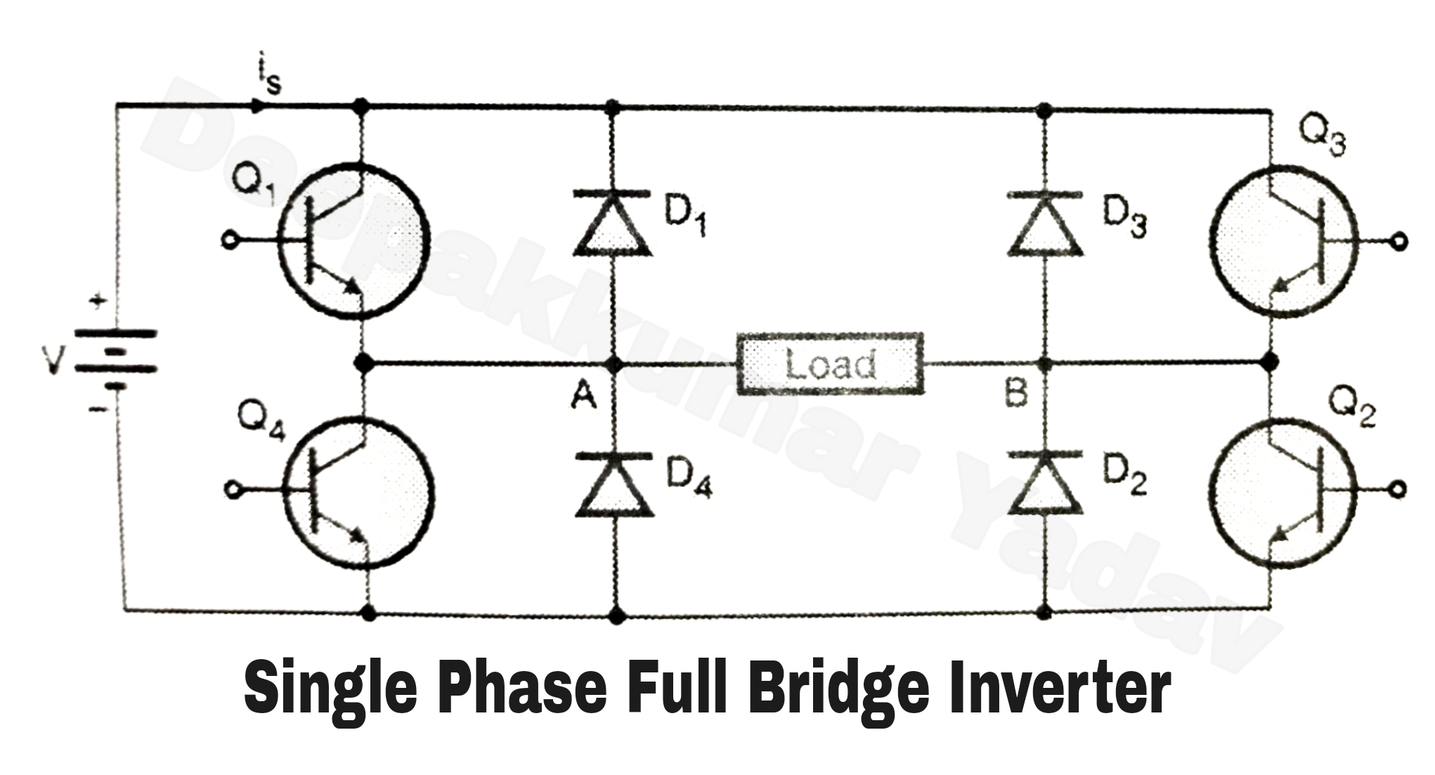
Single Phase Full Bridge Inverter (Square Wave Output)

Full Bridge Inverter: Circuit, Waveforms, Working And Applications

Resources | Powersim, Inc

Three-phase Inverters | Gastón’s writings, works and musings